![]() (Year 2018)
(Year 2018)
Since I found all material necessary to build this Dipmeter in my drawers and because my
colleague wanted to build something similar, I decided to build it after many years. I
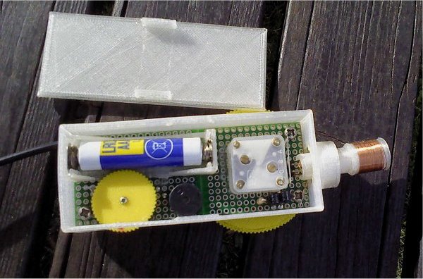
first want to test the circuits on a perforated PCB.
I changed the scheme by B. Kainka. I added a potentiometer with a switch and used the transistor BF494 in the oscillator. With the potentiometer we can adjust the pitch of the indicator, since the oscillator does not oscilate at all frequencyes equally strong.
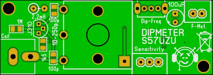
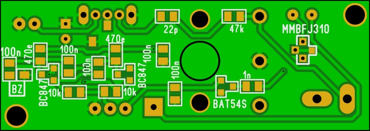
I also made PCB and
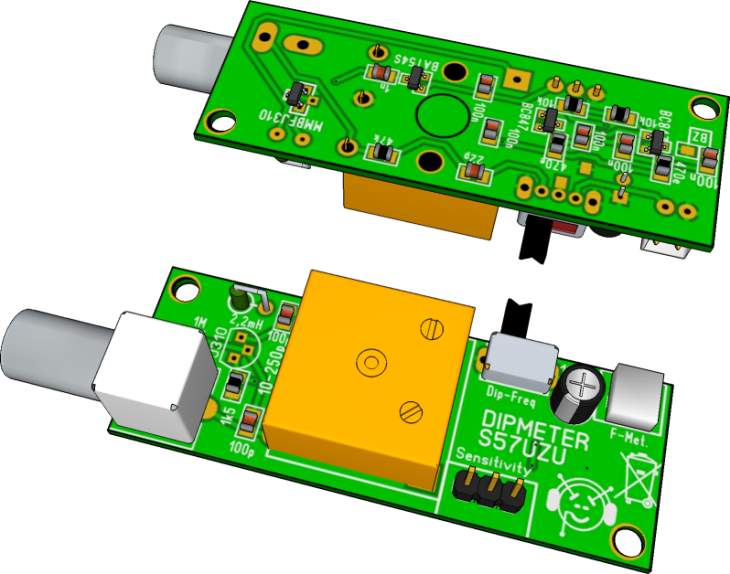
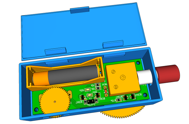
I draw the housing, buttons, battery holder and coils with a free version of Sketchup and I publish all the necessary files for printing plastic parts and they are ready to print with a 3D printer.
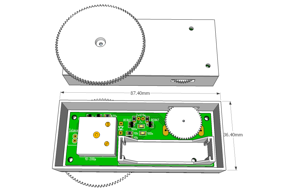
Another version has frequency meter and dimension of about cigarette box. I found it very difficult to make a scale on the variable capacitor button on the upper instrument.
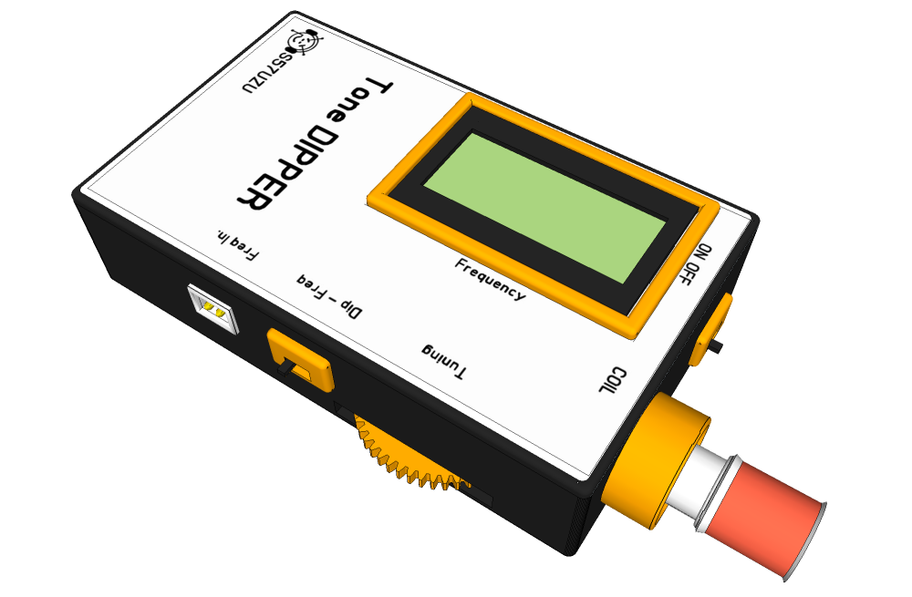
That's why I installed a frequency meter and got rid of the scale. I also installed a switch to turn off the oscillator and at the same time switch the frequency meter to the external source that we want to measure. So we get two instruments in one, but it's still very compact. The frequency meter operates from 1MHz to 500MHz, so it is very useful and belongs to a series of my own devices called CBSP (cigarette-size box projects).
DIP meter with FET
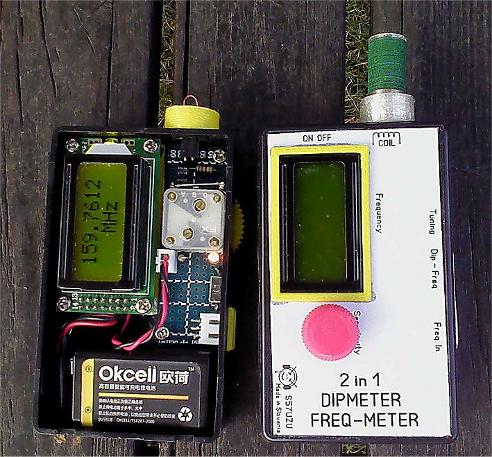
Both devices still in the testing